

The theoretical diesel cycle is a thermodynamic process that describes the operation of diesel engines, which are common in transportation vehicles, power generators, and industrial machinery.
The theoretical cycle of a heat engine is a theoretical approximation of its operation to calculate its performance and is constituted by the physical and chemical transformations that the fuel undergoes during its passage through the engine.
The study of a real cycle taking into account all the numerous variables represents a very complex problem. Therefore, it is currently simplified by resorting to theoretical approaches, based on different simplified assumptions.
Stages of the diesel cycle
This cycle is made up of four main stages: intake, compression, combustion and exhaust. Here is a detailed explanation of each of these stages:
Admission
In this first stage, the piston is at the top of its stroke and the engine cylinder is filled with air at atmospheric pressure. The intake valves open, allowing air to enter the cylinder.
In diesel engines, air is the only fluid introduced at this stage, unlike gasoline engines, where air and fuel are mixed from the beginning.
Compression
Once the cylinder is full of air, the piston begins to descend and compresses the air. During this stage, the temperature and pressure of the air increase significantly due to compression.
The elevated pressure causes the air to reach very high temperatures in preparation for combustion according to the gas law.
Combustion
In the third stage, when the piston is at the top of its compression stroke, diesel fuel is injected into the cylinder. The hot, compressed air causes the fuel to ignite spontaneously due to the high temperature, without the need for a spark as in gasoline engines.
This sudden combustion creates an explosion that forces the piston down forcefully. It is this expansion of gases that generates the mechanical energy used to propel the vehicle or perform useful work, such as generating electricity in a generator.
Exhaust
Finally, after combustion, the piston rises again, pushing the resulting exhaust gases out of the cylinder through the exhaust valves. These gases exit into the environment or are directed through an exhaust system to reduce emissions and noise.
Diesel engine theoretical cycle diagram
 The theoretical cycle of the diesel engine is commonly represented in a diagram called the "Pressure-Volume Diagram" or "PV Diagram". This diagram shows how pressure and volume within the engine cylinder vary during the four stages of the diesel cycle.
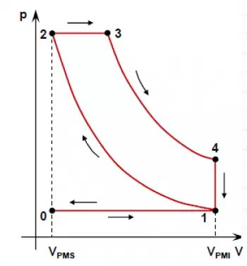
As seen in Com we can see in the figure, the ideal diesel cycle is made up of four thermal lines that represent:
Adiabatic compression (1-2)
The compression stage is carried out without heat exchange, the piston rises, reducing the volume in the cylinder. During this process, air pressure and temperature increase significantly. This is shown on the diagram as a curved line from point 1 to point 2, which represents adiabatic compression.
Constant pressure intake (2-3)
The piston is at the top of its stroke (point 2). During intake, the intake valves are open and the piston descends, increasing the volume in the cylinder and allowing air at atmospheric pressure to enter. This is represented on the diagram as a horizontal line going from point 2 to point 3 representing the entry of air at constant pressure (isobaric) as the volume increases.
Adiabatic expansion in combustion (3-4)
In this stage it is carried out without heat exchange; In it, diesel fuel is injected into the cylinder and ignites due to the high temperature and pressure of the compressed air. During this stage, the pressure increases dramatically as the fuel burns and the gases expand. On the diagram, this is represented as a descending line from point 3 to point 4.
Expulsion of heat at constant volume (4-1)
The last stage is exhaust, in which combustion gases are expelled from the cylinder as the piston moves upward again. This is shown as a horizontal line representing the removal of exhaust gases as the volume increases again (from point 4 to point 1).
Theoretical diesel cycle performance
During transformation 2-3 of introducing heat Q1 at constant pressure, the piston comes into operation, and therefore, the fluid produces work:
![]()
Therefore, the no-flow energy equation becomes
![]()
and the enthalpy h of the fluid is given by the expression
![]()
The equation becomes
![]()
Since the fluid is a perfect gas, we can use, for its enthalpy variation at constant pressure, the expression
![]()
Then, the heat introduced will have the following value:
![]()
It should be noted that in a transformation with the introduction of heat at constant pressure, the value of the enthalpy of the active fluid varies, while in the case of the transformation at constant volume, the internal energy of the fluid varies. Since the subtraction of the heat Q2 is carried out as in the Otto cycle, we can write:
Q 2 =U 4 -U 1
and since the fluid is a perfect gas and the cycle is ideal:
Q 2 =C v (T 4 -T 1 ).
Therefore, the ideal thermal efficiency of the theoretical diesel cycle is:
h e = (heat supplied – heat subtracted)/ heat supplied
expression completely analogous to that found for the ideal performance of the theoretical Otto cycle.
For the 2-3 transformation of combustion at constant pressure we have:

For the adiabatic transformations 1-2 of compression and 3-4 of expansion, we have, respectively:
where from:
and since V 4 =V 1 and T 3 /T 2 =V 3 /V 2 are , we can write:
Substituting this expression into that of the ideal thermal efficiency, we get:
indicating with t' the relationship between the volumes V 3 and V 2 at the end and beginning, respectively, of the combustion phase at constant pressure, to which we will give the name “combustion ratio at constant pressure”, and remembering that
![]()
Finally, we obtain the expression of the ideal thermal efficiency of the theoretical diese cycle l:

In this expression we see that he is, for the diesel cycle, a function of the compression ratio, the combustion ratio at constant pressure and the ratio k between the specific heats.
The expressions of the thermal efficiency of the Otto and diesel cycles differ only by the term in parentheses, which is always greater than 1, and, therefore, it is clear that with the same compression ratio he is greater for the Otto cycle than for the diesel cycle. By reducing t', that is, the heat introduced at constant pressure, the efficiency he of the diesel cycle approaches that of the Otto cycle, with which it coincides for t'=1.