The armature is a component of an electrical machine, responsible for converting electromagnetic energy into mechanical energy (rotary motion) through electromagnetic induction.
This element is magnetically coupled to the inductor, which is the part of the machine where the electromotive force (emf) is generated by induction.
In direct current (DC) motors, the armature is usually located in the rotor, while in asynchronous alternating current (AC) motors, the armature can be located in the stator, which is also known as an induction motor. This design is based on the interaction between the magnetic fields generated by the stator (in AC) and the rotor (in DC).
The armature in direct current motors
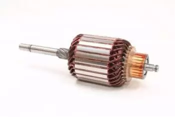
In DC motors, the armature is the rotating part of the machine.
It consists of a drum made of silicon iron sheets, approximately 0.5 mm thick. These sheets are stacked on top of each other and have slots on the outside, where the motor windings are placed. When rotating within the magnetic field generated by the inductor (located in the stator), an electromotive force (emf) is induced in the armature coils, which generates current.
The ends of the coils are connected to copper strips distributed around the periphery of an insulating cylinder called a collector. The collector connects the armature coils to the external electrical circuit by means of carbon brushes that rub against the strips. This system is responsible for the unidirectional current in the coils, allowing the motor to rotate continuously in one direction.
The commutator, made up of the coils, plays a crucial role, as it allows the direction of the current in the coils to be periodically reversed, ensuring that the motor continues to rotate. Although traditionally DC motors used this system with brushes and a commutator, nowadays there are also brushless DC motors (BLDC, Brushless DC), which use electronic commutation to control the flow of current without the need for physical contact.
The armature in alternating current motors (induction motors)
In alternating current motors, especially in asynchronous induction motors, the armature is also known as the rotor.
This rotor, which is located in the moving part of the motor, interacts with the magnetic field generated by the stator. In these motors, the current is not supplied directly to the rotor, but is induced in it due to the variable magnetic field created by the currents in the stator. This induction generates a magnetic field in the rotor that interacts with the magnetic field of the stator, producing the rotary motion.
The rotor of these motors is usually of a squirrel cage design, where the conductors are arranged in a closed arrangement within the rotor, with no direct connection to the external circuit. The current induced in these conductors is what causes the rotor to rotate within the magnetic field of the stator.
The armature in alternators
In alternators, which are machines that convert mechanical energy into electrical energy in the form of alternating current, the armature is located in the rotor, while the stator acts as the inductor.
In these generators, the rotor is made up of a hollow cylinder made of silicon steel sheets, arranged one on top of the other. This cylinder has slots inside, where the coils are inserted.
When the rotor rotates within the magnetic field created by the stator, an electromotive force is induced in the rotor coils, generating alternating current.
On the outside of the alternator casing are the terminals that connect the armature coils to the external electrical circuit, where the generated current is delivered. These terminals allow the induced alternating current to flow towards the electrical system for which it is intended.
Materials and armature efficiency
The armature is made of highly efficient conductive materials, such as copper or aluminium, due to their excellent electrical properties.
In addition, silicon iron sheets are used to form the core of the armature, as they help reduce eddy current losses (Foucault currents) and hysteresis losses by minimizing resistance to the passage of magnetic flux.
These losses are one of the sources of inefficiency in electric motors, so optimizing the armature design, reducing the air gap distance and improving materials, is key to increasing the machine's performance.
Other types of electric motors
There are other types of motors in which the armature plays a crucial role, such as synchronous motors and stepper motors.
In synchronous motors, the rotor rotates at the same speed as the stator's magnetic field, making them ideal for applications requiring a constant speed. In stepper motors, the armature (rotor) moves in discrete steps, allowing for precise control of motion.
Armature coil in electric motor
Armature windings are a crucial component in the design of electric motors, as they are responsible for generating the electric current through interaction with the magnetic field.
These windings are the coiled conductors that, when subjected to a variable magnetic field, induce a current that generates the electromotive force (emf) necessary to produce movement in electric motors.
Types of windings in the armature
Armature windings can be designed in various ways depending on the type of motor and its operating requirements. The main types of windings used in electric motor armatures are described below:
Slot winding
This is the most common design in electric motors. In this type of winding, the conductors (usually copper or aluminum) are placed in slots that are present in the armature core (or rotor in some cases).
The slots are designed to house the coils compactly, allowing for efficient distribution of the magnetic field.
This type of winding can be single layer or multi-layer. Multi-layer windings are used in higher power motors as they allow a greater number of turns of wire in each slot, which increases the motor's current capacity.
Spiral winding
In this type of winding, the conductor is wound continuously in a spiral along the armature. This design is most common in small power motors or brushless motors (such as BLDC motors). The spiral arrangement allows for better induction management and current distribution.
Ring winding
In DC motors, especially in the early versions, the windings were usually placed in rings surrounding the armature core.
This design was less efficient, as the induced current had to pass through a larger space due to the air gap, resulting in a weaker magnetic field. However, this design was replaced by slots to improve efficiency and reduce friction losses.
Characteristics of armature windings
Armature windings have a number of important characteristics that affect the performance of an electric motor:
Number of turns of cable
The number of turns in the winding has a direct impact on the electromotive force generated. The more turns, the greater the induced emf, which increases the efficiency and power of the motor. However, more turns also mean greater resistance and therefore greater heat dissipation. It is essential to find a proper balance between the number of turns and the resistance of the winding.
Winding distribution
The way the conductors are distributed in the slots of the armature affects the quality of the magnetic field generated and the efficiency of the motor. The windings are designed to distribute the current evenly throughout the armature, minimizing eddy current losses (energy losses due to unwanted magnetic fields).
Type of conductive material
The materials used for the windings, usually copper or aluminum, must have high conductivity to maximize the efficiency of the induced current. Copper is the preferred material due to its excellent electrical conductivity, although aluminum is used in lower-cost motors due to its lower density and cost.
Isolation
Armature windings must be insulated to prevent short circuits between the coils and the armature core. The insulation must also be resistant to high temperatures generated by electrical currents. Common materials for insulation include epoxy resins, insulating paints, and impregnated paper. In addition, insulation helps reduce eddy current losses.
Slot orientation
The orientation of the slots in the armature directly affects the quality of the induced magnetic field. The slots can be symmetrical or asymmetrical. In high-efficiency motors, the slot arrangement is optimized to reduce harmonic losses and improve magnetic flux distribution.