The Stirling cycle is a thermodynamic cycle that describes the operation of a class of equipment (generating or operating machines). The cycle describes the original Stirling engine that was invented and patented in 1816 by Reverend Robert Stirling, helped substantially by his engineer brother.
The Stirling engine is an external combustion engine. This characteristic differentiates it from other types of engines such as the Otto engine or the diesel engine, which are internal combustion engines. Both engines work according to the Otto cycle and the diesel cycle respectively.
The Stirling cycle is reversible. This cycle can be used by generators to obtain mechanical energy from the application of heat and a source of cold (a heat pump). This cycle can also be used to obtain thermal energy (heat) or cold by applying mechanical energy.
The Stirling cycle is a closed cycle, that is, the fluid that makes the cycle is permanently contained in the device that performs the cycle and is not exchanged with the outside. A specific characteristic of the original cycle is that it is regenerative. A regenerative res cycle when it uses a particular internal device called a regenerator. A regenerator is a heat exchanger-accumulator that increases efficiency.
The cycle is similar to many other cycles, where there are basically four phases:
- compression phase,
- Phase of heat delivery to the fluid,
- Fluid expansion phase
- Fluid heat removal phase.
As is often the case in the comparison between ideal cycles and real cycles, the real cycle is not so neatly separated into distinct and distinct phases. In the Stirling cycle, the overlaps of the different phases are particularly striking.
ideal Stirling cycle
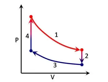
 The ideal Stirling cycle consists of four thermodynamic phases acting on the cycle fluid (see diagram to the right):
- From point 1 to point 2: isothermal expansion. The expansion compartment is heated from the outside and the contained gas has an isothermal expansion.
- From point 2 to point 3: hot gas transfer at constant volume or isochoric transformation; the gas passes through the regenerator, giving it part of the heat, which will remain available for a subsequent phase.
- From point 3 to point 4: compression isothermal, the fluid in the compression space cools, the compression is imagined to be isothermal.
- From point 4 to point 1: heat transfer at constant volume; the fluid flows back through the regenerator, recovering heat from the regenerator itself.
While the theoretical approach is conceptually simple, the actual thermodynamic analysis has engaged physicists for a long time. Creating an analysis model of the real cycle has not turned out to be a trivial task, since the ideal cycle bears only a distant resemblance to the real thing.
The analytical problem of the regenerator (the central heat exchanger in the Stirling cycle) was judged to be one of the most complex levels to be found in Engineering.
Movement of mechanical devices in Stirling engines
Most of the texts dealing with the Stirling cycle follow the highly simplified model of the ideal Stirling cycle. This way of proceeding is misleading given that if we calculate the areas of the ideal cycle (theoretically) they appear to have very high energy yields at work. However, this would require mechanisms that are physically impossible to realize.
Actually, it is necessary to imagine a practical mechanism that manages to obtain something that resembles the ideal cycle, using the real and usual mechanical parts, such as pistons, and the crank mechanisms linked to them.
The use of kinematics related to rotation produces, understandably, sinusoidal type movements of the parts. The set of sinusoidal movements, often with "crossed" pistons, transform the cycle, represented by straight lines or pure curves. into a kind of flattened "bean", in which the internal area (and therefore the work) is drastically reduced.
Some kinematics, such as the so-called "Ross yoke" (Ross connecting rod), (a compromise link between the crosshead and a simple lever transmission), produce almost sinusoidal motion. Other kinematics produce different movements, the possible kinematics govern the possible solutions, but most of the possible movements are not always compatible with all the contrast conditions of an ideal system.
Reverse Stirling Cycle
On the one hand, it is difficult to establish efficient heat with pulsation, and to efficiently extract energy from the pulsator system. On the other hand, it is also even more difficult to practice the reverse cycle. The reverse cycle involves obtaining heat or cold through the administration of mechanical energy.
With mechanical energy, a pressure is generated in a confined fluid. The pressure to the fluid implies a compression and the generation of heat. On the other hand, the mechanical energy supplied can generate a depression to the fluid, an expansion of the same. This expansion absorbs heat energy, that is, cooling. This is what is achieved in the Stirling refrigeration machine, obtained with conventional mechanical devices, with (cranks and pistons), or with the inverse use of the thermo-acoustic motor, where the mechanical pulsation is provided by resonant systems (linear motors), plates piezoelectric) that operate at much higher frequencies.
PV diagram of a real cycle
 PV diagram of a real Stirling cycle; four angular positions of the crank of the machine that executes the cycle are indicated
The actual cycle can be represented on a pressure-volume (PV) diagram as a closed curve with a shape; this curve represents, with different values of pressure and temperature, most of the real Stirling cycles.